Most industrial types of equipment are inductive loads hence, they required two kinds of power been consumed by them (kW - to perform the actual work and kVAR - reactive power to sustain the magnetic field of the load).
Example of inductive load - Electric motors, Induction furnaces, Lighting ballasts, etc basically loads with the composition of coils for their design.
While kW is the useful power required to keep the machine running. The kVAR basically does not perform any useful work except to help to sustain the magnetic field in the equipment.
For example - if you had an electric motor that was operating at 100kW and the apparent power was 125kVA. Hence, power factor will be 0.8 (kW/kVA = 100/125 = 0.8pf). This means kVA decreases if pf increases.
As an example -
A 100kW load operating at 142kVA will have 0.7pf (70% efficient) and at 105kVA the pf will be 0.95(95%). This means the more you correct your pf the lesser the kVA that will be consumed and the lesser the utility you are going to pay.
One common method of improving the power factor is connecting capacitors in parallel to the load.
When apparent power (kVA) is greater than working power (kW), the utility must supply the excess reactive current plus the working current. Power capacitors act as reactive current generators.
By providing the reactive current, they reduce the total amount of current your system must draw from the utility
What do I save by Installing Capacitor Bank
- Reduced electric utility bill
- Reduce system maintenance
- Increase life span of an equipment
- Reduce losses
- Improve voltage
How much can I save by Installing Capacitor Banks
Scenario 1 (kVA billing) -
Assume an uncorrected 460kVA demand, 480V, three-phase at 0.87 power factor (normally good)
Billing:
$4.75/kVA demand
Correct to 0.97 power factor
Solution:
kVA x power factor = kW
460 x 0.87 = 400kW actual demand
kW/PF = kVA
400/0.97 = 412 corrected billing demand
From below table (Table 6) kW multipliers, to raise the power factor from 0.87 to 0.97 requires capacitor:
Multiplier of 0.316 x kW
0.316 x 400 = 126kVAR (use 140kVAR)
Uncorrected original billing:
460kVA x $4.75 = ($2185 / month) - ($1957) = $228/month savings = $228 x 12 = $2,736 annual savings
Corrected new billing:
412kVA x $4.75 = $1957/month
140kVAR, 480V capacitor cost $1600 (installation extra)
This capacitor pays for itself in less than eight month
Kilowatt Demand Billing with Power Factor Adjustment
The utility charges according to the kW demand and adds a surcharge or adjustment for power factor. The adjustment may be a multiplier applied to kW demand. The following formula shows a billing based on a 90% power factor:
kW demand x 0.9 (divided by ) actual power factor
If a power factor was 0.84, the utility would require 7% increase in billing as shown below:
kW x 0.90 (divided by) 0.84 = 107 (multiplier)
Some utilities charge for low power factor but give credit or bonus for power above a certain level.
Scenario 1:
Assume a 400kW load, 87% power factor with the following utility tariff
Demand charges:
First 40kW @ $10.00/kW monthly billing demand
Next 160kW @ $9.50/kW
Next 800kW @ $9.00/kW
All over 1000kW @ $8.50/kW
Power factor clause:
Rates are based on a power factor of 90% or higher. When the power factor
is less than 85%, the demand will be increased 1% for each 1%
that the power factor is below 90%. If the power factor is higher
than 95%, the demand will be decreased 1% for each 1% that the
power factor is above 90%.
There would be no penalty for 87% power factor. However, a
bonus could be credited if the power factor were raised to 96%.
To raise an 87% power factor to 96%, refer to Table 6.
Find 0.275 x 400 kW = 110 kVAR. (Select 120 kVAR to ensure the
maintenance of the 96% level.)
To calculate savings:
Normal 400 kW billing demand
First 40 kW @ $10.00 = $ 400.00
Next 160 kW @ $ 9.50 = $1520.00
Bal. 200 kW @ $ 9.00 = $1800.00
Total(addition of normal+first+next) 400 kW $3720.00 normal monthly billing
New billing:
kW x 0.90 (divided by) New power factor = 400 x 0.90 (divided by) 0.96 = 375kW demand
First 40 kW @ $10.00 = $ 400.00
Next 160 kW @ $ 9.50 = $1520.00
Bal. 175 kW @ $ 9.00 = $1575.00
$3495.00 power factor adjusted billing


Further instruction for Table 6:1. Find the present power factor in column one2. Read across to optimum power factor column3. Multiply that number by kW demand
Example:If your plant consumes 410 kW, is currently operating at 73% power
factor, and you want to correct power factor to 95%, you would: 1. Find 0.73 in column one2. Read across to 0.95 column3. Multiply 0.607 by 410 = 2494. You need 250kVAR to bring your plant to 95% power factor
If you don’t know the existing power factor level of your plant,
you will have to calculate it before using Table 6 on the
following page. To calculate existing power factor: kW divided by
kVA = power factor.
How can I select the right capacitors for my specific application needs?
Once you’ve decided that your facility can benefit from power factor
correction, you’ll need to choose the optimum type, size, and the number
of capacitors for your plant.
There are two basic types of capacitor installations: individual
capacitors on linear or sinusoidal loads, and banks of fixed or
automatically switched capacitors at the feeder or substation.
Individual vs. banked installations
Advantages of individual capacitors at the load:
• Complete control; capacitors cannot cause problems
on the line during light load conditions
• No need for separate switching; motor always operates
with capacitor
• Improved motor performance due to more efficient power
use and reduced voltage drops
• Motors and capacitors can be easily relocated together
• Easier to select the right capacitor for the load
• Reduced line losses
• Increased system capacity
Advantages of bank installations at the feeder or substation:
• Lower cost per kVAR
• Total plant power factor improved—reduces or eliminates all
forms of kVAR charges
• Automatic switching ensures the exact amount of power factor
correction, eliminates over-capacitance and resulting overvoltage's
Consider the particular needs of your plant
When deciding which type of capacitor installation best meets your
needs, you’ll have to weigh the advantages and disadvantages of
each and consider several plant variables, including load type, load
size, load constancy, load capacity, motor starting methods, and
manner of utility billing.
Load type
If your plant has many large motors, 50 hp and above, it is usually
economical to install one capacitor per motor and switch the
capacitor and motor together. If your plant consists of many small
motors, 1/2 to 25 hp, you can group the motors and install one
capacitor at a central point in the distribution system. Often, the
best solution for plants with large and small motors is to use both
types of capacitor installations.
Load size
Facilities with large loads benefit from a combination of individual
load, group load, and banks of fixed and automatically-switched
capacitor units. A small facility, on the other hand, may require only
one capacitor on the control board.
Sometimes, only an isolated trouble spot requires power factor
correction. This may be the case if your plant has welding machines,
induction heaters, or DC drives. If a particular feeder serving a low
power factor load is corrected, it may raise overall plant power factor
enough that additional capacitors are unnecessary.
Load constancy
If your facility operates around the clock and has a constant load
demand, fixed capacitors offer the greatest economy. If the load is
determined by eight-hour shifts five days a week, you’ll want more
switched units to decrease capacitance during times of reduced load.
Load capacity
If your feeders or transformers are overloaded, or if you wish
to add additional load to already loaded lines, correction must be
applied at the load. If your facility has surplus amperage, you can
install capacitor banks at main feeders. If the load varies a great deal,
automatic switching is probably the answer.
Utility billing
The severity of the local electric utility tariff for power factor will affect
your payback and ROI. In many areas, an optimally designed power
factor correction system will pay for itself in less than two years.
How much kVAR do I need?
The unit for rating power factor capacitors is a kVAR, equal to
1000 volt-amperes of reactive power. The kVAR rating signifies how
much reactive power the capacitor will provide.
Sizing capacitors for individual motor loads
To size capacitors for individual motor loads, use Table 3 on the
following page. Simply look up the type of motor frame, RPM, and
horsepower. The charts indicate the kVAR rating you need to bring
power factor to 95%. The charts also indicate how much current is
reduced when capacitors are installed.
Sizing capacitors for entire plant loads
If you know the total kW consumption of your plant, its present
power factor, and the power factor you’re aiming for, you can use
Table 6 to select the capacitor

Where should I install capacitors
in my plant distribution system?
At the Load
Because capacitors act as kVAR generators, the most efficient place
to install them is directly at the motor, where kVAR is consumed.
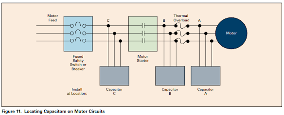
Three options exist for installing capacitors at the motor. Use
Figure 10 through Figure 16 and the information below to
determine which option is best for each motor.
Location A—motor side of overload relay
• New motor installations in which overloads can be sized
in accordance with the reduced current draw
• Existing motors when no overload change is required
Location B—line side of the starter
• Existing motors when overload rating surpasses code
Location Cline side of the starter
• Motors that are jogged, plugged, reversed
• Multi-speed motors
• Starters with open transition and starters that
disconnect/reconnect capacitor during cycle
• Motors that start frequently
• Motor loads with high inertia, where disconnecting the motor
with the capacitor can turn the motor into a self-excited generator
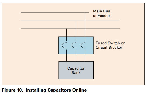
At the Service Feeder
When correcting entire plant loads, capacitor banks can be installed
at the service entrance, if load conditions and transformer size
permit. If the amount of correction is too large, some capacitors can
be installed at individual motors or branch circuits.
When capacitors are connected to the bus, feeder, motor control
center, or switchboard, a disconnect and overcurrent protection
must be provided.
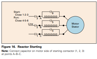
Locating capacitors on reduced voltage and multi-speed motors


What about maintenance?
Capacitors have no moving parts to wear out and require very little
maintenance. Check fuses on a regular basis. If high voltages,
harmonics, switching surges, or vibration exists, fuses should be
checked more frequently.
Capacitors from Eaton operate warm to the touch. If the case is
cold, check for blown fuses, open switches, or other power losses.
Also check for bulging cases and puffed-up covers, which signal
operation of the capacitor interrupter.
source: Power Factor Correction by Eaton Technical Data SA02607001E
Thanks for this explicit explanation.
ReplyDeleteThanks for sharing this in-depth information on power factor correction and capacitor installation! It's really helpful to understand the importance of power factor correction and how it can benefit industrial facilities. Know more about the best electrical engineering colleges in coimbatore
ReplyDelete