Contactors are material that are used for switching
electrical power circuit. They are very similar to a relay but are used for
switching high power circuit i.e 415V or more.
Contactors are mostly used for switching 3-phase power from
the supply to load through their power contact to control loads such as: motor,
generator e.t.c either to switch them ON or OFF.
Basic Principle of Operation
It works with the principle of electromagnetic induction i.e
when current passes through a metallic conductor it tends to exhibit and
develop a magnetic property. The contactor is typically made of laminated core
material to generate the require electromagnet. So, when current flows through
it, magnetic property is develop on this core and causes the contact L1,L2and
L3 to close with T1, T2, T3 and thus allow the passage of the 3-phase supply to
the load.
PARTS OF A CONTACTOR
-The Power Contacts
- The control contact / auxiliary contact
Contactor coil

The power contact is the portion that connects the load the
load to the 3-phase power supply and can either be at closed or opened
position. When the contactor is closed, it allow flow of current to the load
and when open it stops the flow of current to the load. It is normally label
L1, L2, L3, 13 on the incoming supply side and T1, T2,T3,14 on the outgoing
supply end.
The 13 and 14(NO) is an auxiliary contact of the contactor
and mostly serve the function of a control terminal of the contactor
Image….
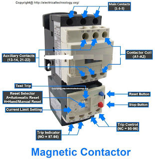

The contactor coil usually label A1 and A2 serves as the
portion to energise the contact. We a single phase is supply to this A1 and A2,
the contactor energizes closing the power contact of L1 to T1, L2 to T2, L3 to
T3 and 13 to 14. It is the energizing of this contactor coil that actually sets
the power contact working thereby transferring the 3-phase from the supply to
the load end
Testing the contactor
Basically, there are two major ways of testing for good operation
of a contactor
1.
Dead testing
2.
Live testing
Dead test on the contactor coil
In this test, we do not need to supply 230V to the coil of
the contactor (A1 and A2). All we need to do here is just to press the spring
return part of the contactor.
1. Set your multimeter to resistance test

2. Set the multimeter to 2k on the resistance range
3. Place the two probe of the multimeter on the two coil terminal of the contactor (A1 and A2). You should get a resistance value on the DMM.
If you are not getting reading on your multimeter, then the contactor contact could be bad.
NOTE: Dead test on the contactor contact
The contact of the contactor are the moving part of the contactor. Most contactor has there contacts in the Normally Open(NO) state (by default) so that when power is applied to the coil of the contactor, the contactor will then transit from NO to Normally Close (NC).
And how is the live test carried out
ReplyDelete