Insulation Resistance of Equipment's
Electrical equipment/material has an insulation resistance property that needs to be monitored on a scheduled basis to avoid sudden breakdown of such equipment.A regular testing of electrical equipment insulation is strongly recommended to prevent electrical shock hazard to personnel, damage to equipment itself and other plant devices.
When you buy a new electric motor or transformer etc the nature of the copper coil used in winding this equipment is still new because the copper winding has not been subjected to operating condition (except during factory acceptance testing) as operation condition will subject the winding to heat and insulation deterioration.
In fact, this is the same for electrical cable, a new cable (made of conductor and insulator). The conductor has a very good isolation/insulation to the insulator(PVC insulation) of its body but when the cable is subject to usage and as current follows through the cable increases, the conductor temperature will also rise which will be affecting the insulation of the cable PVC and overtime this insulation(PVC) can be totally affected and the cable insulation will breakdown leading to electrical spark, shock and in some cases fire or causing protection devices like fuse and circuit breaker to trip/open.
So, good insulation will always have a higher resistance and weak insulation will have a lower resistance when measured with an insulation resistance tester.
When performing insulation resistance test. The equipment is subjected to a higher voltage greater than its nameplate rating and the meter gives a corresponding resistance base on the condition of the equipment resistance (e. winding resistance, insulation of cable PVC etc)
 |
| Observation and summary of IR test result |
What damage equipment insulation?
When your plant electrical system and equipment are new, the electrical
insulation should be in top notch shape. Furthermore, manufacturers of wire,
cable, motors, and so on have continually improved their insulation's for
services in industry.
However electrical insulation of an equipment can fail due to the following reason –
mechanical damage,
vibration,
excessive
heat or cold,
dirt,
oil,
corrosive vapors,
moisture from processes, or just the
humidity on a muggy day.
aging
Equipment for conducting insulation resistance test
- Megohmmeter with a time test functionality
- Temperature indicator.
Types of Insulation Resistance Test
1. Spot Reading Test -
In this method, you simply connect the Megger instrument across the
insulation to be tested and operate it for a short, specific time period
(60 seconds is usually recommended). The spot reading test should only be carried out when the winding temperature is above the dew point (dew point temperature is the temperature at which the moisture vapor in the air condenses as a liquid).
The winding temperature must be recorded before the test is carried and the result be recorded along with the winding temperature so that the result can be properly analysed.
Application of Spot Reading Test
a. If the apparatus you are testing has very small capacitance, such as a
short run of house wiring, the spot reading test is all that is necessary.
Which value is better?
As a general rule of thumb, the test result should be at least 1megaohm per 1000V injected voltage from the megoohm tester.
In newer very good equipment condition, this value can will be greater than 1megaOhm which is very fine (the higher the resistance; the better the equipment performance) however, if the resistance is lower than 1megaohm at tester 1000V then the equipment should be considered for repair/replacement/maintenance.
By taking readings periodically and recording them, you have a better basis
of judging the actual insulation condition. Any persistent downward trend
is usually fair warning of trouble ahead, even though the readings may be
higher than the suggested minimum safe values. Equally true, as long as
your periodic readings are consistent, they may be ok, even though lower
than the recommended minimum values.

Example of variation of insulation resistance over a period of years
At point A, the effect of aging and dust accumulation is shown by decreasing values
At point B, the sharp drop indicates and insulation failure
At point C, the insulation resistance value after maintenance (such as rewinding or rebaking of the coil)
2. Time - Resistance Test / Absorption Test
This method is fairly independent of temperature and often can give
you conclusive information without records of past tests. It is based on
the absorption effect of good insulation compared to that of moist or
contaminated insulation.
In this test, different readings are taking at specific time and the readings are recorded.
The megohmeter is set to the require test voltage example (1000V) and applied to the equipment winding terminal at different time intervals.
Note that good insulation shows a continual increase in resistance (less
current – see curve A) over a period of time (in the order of 5 to 10 minutes).

 |
| Typical time resistance test plot value The above plot shows how a 60-second test would appear for good and perhaps bad insulation. When the insulation is in good shape, the 60-second reading is higher than the 30-second reading. |
Benefits
- It is independent of equipment size
- The increase in resistance for clean and dry insulation occurs
in the same manner whether an equipment is large or small
- It gives a clearer result even when a spot reading test shows a fine result
As an example -
Let’s say the spot reading on a synchronous motor was 10
megohms. Now, let’s assume that the time-resistance test shows that the
insulation resistance holds steady at 10 megohms while you hold voltage up
to 60 seconds. This means there may be dirt or moisture in the windings that
bears watching. On the other hand, if the pointer shows a gradual increase
between the 30-second and the 60-second checks, then you’re reasonably
sure the winding's are in good shape.
3. DAR Test (Di electric absorption test)
In this method, an operator applies two or more test voltages in steps where the recommended test step voltage is 1 to 5. At each step, test voltages should be applied for the same length of time usually, 60 seconds. The application of increased voltage creates electrical stresses on internal insulation cracks. This can reveal aging, physical damage in relatively dry and clean insulation which could not be detected at lower voltage.
If the ratio is a 10-minute
reading divided by a 1-minute reading, the value is called the polarization
index.
Interpretation of test results
- A very good insulation should provide roughly the same value despite changes in test voltage
- If resistance value decreases drastically as test voltage increases, this should serve as a warning that the insulation quality may be deteriorating due to dirt, moisture, ageing etc
 |
| Condition of Insulation Indicated by Dielectric Absorption Ratios |
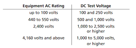
Commonly used DC test voltages for routine maintenance are as follows:
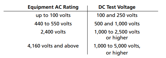
NOTE: Test voltages used for proof testing of equipment are considerably higher
than those used for routine maintenance.
Proof Test Voltages for Rotating Equipment:
Factory AC Test = 2 x Nameplate Rating + 1000 volts
DC Proof Test on Installation = 0.8 x Factory AC Test x 1.6
DC Proof Test After Service = 0.6 x Factory AC Test x 1.6
Example:
Motor with 2,400 VAC nameplate rating–
Factory AC Test = 2(2,400) +1,000 = 5,800 VAC
Max. DC Test on Installation = 0.8(5,800)1.6 = 7,424 VDC
Max. DC Test After Service = 0.6(5,800)1.6 = 5,568 VDC
-
Comments
Post a Comment